EIU-510
Engine Interface Unit
The EIU‑510 is a high‑power engine interface unit designed to operate alongside the TAG‑510 ECU, providing the drive stages and monitoring required for modern hybrid, turbocharged race engines with up to eight cylinders. By separating high‑current actuation from the core ECU, the EIU‑510 enables robust control of ignition, injection and fuel systems while maintaining reliable, high‑speed communication with the host ECU.
Documents
Performance at every stage.
The EIU‑510 is a dedicated power stage for the engine, handling high‑current outputs and diagnostics while exchanging configuration and data with the ECU over CAN.
Drives ignition, injection and fuel pump systems
Supports up to 8‑cylinder direct‑injection turbocharged engines
Designed for race car engine environments
Engineered as a companion unit to the TAG‑510 ECU
System architecture
The EIU‑510 forms part of a distributed engine control architecture, separating high‑power actuation from core control logic. This approach reduces electrical and thermal stress on the ECU while allowing the system to scale with increasing engine complexity.
Drive outputs
Output capability | Summary |
|---|---|
Injector drive stages | 12 dedicated injector drivers with multi‑stage current control |
Ignition drive stages | 8 high‑current ignition drivers |
Fuel pump control | 2 high‑pressure fuel pump drivers |
Auxiliary drive stages | Outputs available for lambda heaters and actuator control |
Diagnostics access | User‑configurable diagnostic outputs for system monitoring |
Inputs and engine sensing
Input type | Description |
|---|---|
Injection triggers | Configurable trigger inputs for injector control |
Ignition triggers | Dedicated ignition trigger inputs |
Fuel pump triggers | Configurable fuel pump trigger inputs |
Temperature sensing | K‑type thermocouple inputs |
Lambda sensing | Wide‑band lambda sensor interfaces |
System inputs | Ignition switch and service / force‑boot input |
Internal sensing | Integrated tri‑axis accelerometer |
Communication & integration
Interface | Capability |
|---|---|
CAN | Multiple CAN FD / CAN 2.0 interfaces for control and data logging |
LIN | Single LIN interface |
Configuration | ECU‑managed configuration and synchronisation |
Data handling | High‑speed data exchange with the host ECU |
Electrical architecture
Aspect | Overview |
|---|---|
Power strategy | Designed to be supplied by an external system power regulator |
Supply rails | Separate supplies for internal logic, injection and ignition systems |
System intent | Electrical separation of control and high‑current actuation |
Electrical architecture
Aspect | Overview |
|---|---|
Power strategy | Designed to be supplied by an external system power regulator |
Supply rails | Separate supplies for internal logic, injection and ignition systems |
System intent | Electrical separation of control and high‑current actuation |
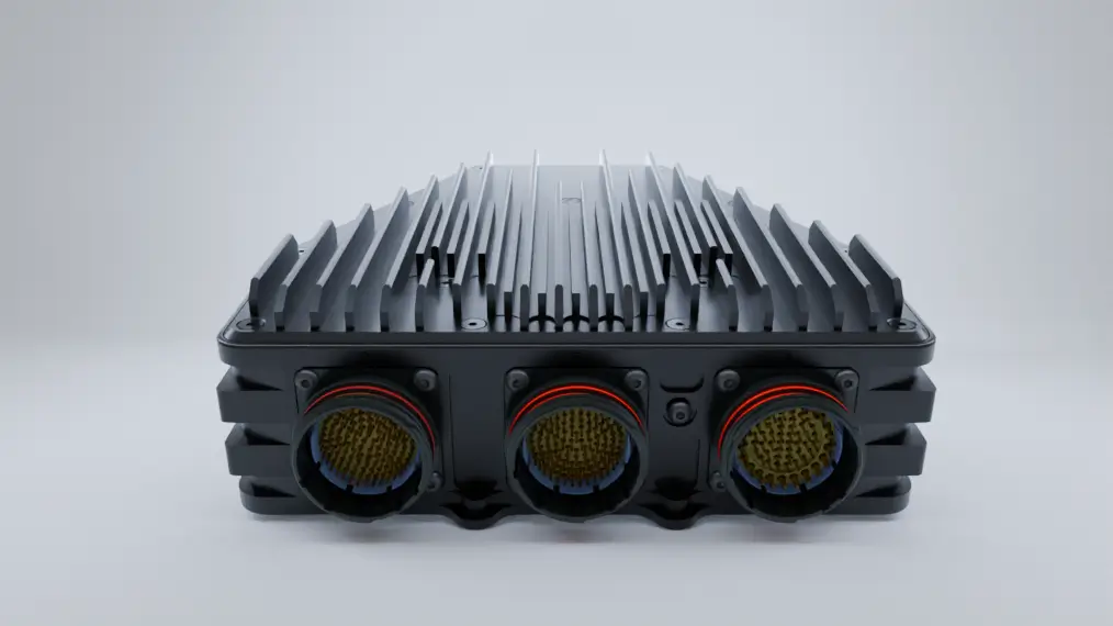
Mechanical & environmental
Attribute | Specification |
|---|---|
Enclosure | Hard‑anodised aluminium housing |
Form factor | Compact rectangular unit |
Environmental sealing | IP‑rated with sealed lids |
Operating environment | Designed for high‑vibration, high‑temperature engine bays |
Cooling strategy | Internal temperature monitoring supported |
Compliance
Item | Details |
|---|---|
Environmental compliance | RoHS compliant |
EMC | Meets automotive EMC requirements |
Service interval | Recommended 12‑month inspection cycle |